
With the increasing need for energy conservation and efficiency in electrical machinery in recent years, VFDs (variable frequency drives) are being used more than ever in motor circuits. Benefits include increased efficiency by limiting energy consumption, and decreased wear of the equipment. These improvements come at a cost in the form of introduced EMI (electromagnetic interference) and this is where the VFD cable comes into play.
VFD Cable Construction
Typical power cables are designed to carry electrical power at a fixed frequency of 60Hz. VFD cables are specially designed to carry power with varying frequencies, and all of the by-product that comes along with it. There is no specific CSA standard for VFD cables, which means no unique CSA reference like ‘Teck90’ either. For this reason, you will not find any reference to VFD cable in Table 19 of the CE Code. The VFD cables are typically built to non-VFD cable CSA standards (e.g., CSA C22.2 No. 174, CSA C22.2 No. 230, CSA C68.10) and a selection of components are integrated into the cable make-up to handle electrical noise (voltage spikes, reflected waves, harmonic currents, common-mode voltage, and RFI/EMI interference) that is generated from the ‘Variable Frequency Drive’. We will look at these components in more detail in this newsletter.
The Role of VFD Cable in the Variable Frequency Drive ‘System’
A VFD System consists of the Source Power, the VFD, Power Cable, and the Motor. Our view may be biased, but we believe that the VFD cable is one of, if not the most important components to ensure the system operates as it has been designed to, and with minimal down time.
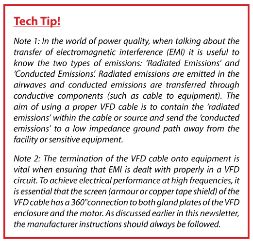
To perform its role in a VFD system, the power cable must execute two functions in unison; Safely carry electrical power from the VFD to the electrical load plus, safely contain, manage, and carry system EMI (electromagnetic interference) to the ground via the correct route.
A properly specified and installed VFD cable can effectively manage circuit EMI that can otherwise contribute to unwanted mechanical and electrical problems, on the equipment and the local facility. It’s worth paying attention to specifying and installing this component. After all, a VFD system is an investment by the facility owner to lower facility operational and maintenance costs, not introduce electrical problems.
Choosing a VFD cable
How do I specify a VFD cable? The VFD cable is typically only required between the VFD and the motor. We recommend first contacting the VFD equipment manufacturer to request the cable specification and termination instructions; they are the system experts. If this is not possible, Texcan’s support team can help recommend specific cable types and availability.
Texcan stocks CCW (Continuous Corrugated Armour) VFD cables and has direct access to a full range of VFD cables for all applications and voltages. As we have said before in our newsletters, the earlier you get Texcan involved the more we can do to help you get ‘what you want, when you need it’.
Note. It is essential that the VFD cable screen has a 360° connection. Texcan stocks suitable cable connectors and offers a ‘Fitted System’ for cable connectors & termination kits up to 69kV. Contact our Product Manager Keith.Thom@texcan.com for connector and termination kit support.
Specialist Components of VFD Cables
VFD Cables come in a range of constructions to serve various applications. Below, we look at the different construction styles and properties of VFD cables, that allow them to perform as a key part of a Variable Frequency Drive System.
Overall Shield
The main function of the overall shield in a VFD cable is to contain radiated EMI. The different types of overall shields utilized in VFD cables are:
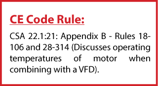
Continuous Corrugated Welded Armour (CCW)
CCW is a continuously welded aluminum shield without gaps throughout its length. TECK cable with AIA (aluminum interlocked armour) does not contain EMI as effectively since it is not continuous. If an AIA cable is used for a VFD application it is recommended to have an overall copper tape shield with at least 25% overlap.
Note. When system voltage is ≥ 5000V the power conductors in a VFD are required to be shielded.
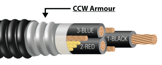
Helically Applied Copper Tape (25% Overlap)
Copper tape serves the function of an overall shield in a non-armoured VFD cable. To provide 100% coverage the copper tape screen should be 5mm thick and have a 25% overlap.
Note. In cables ≥ 5000V with shielded power conductors an overall cable shield is not typically provided.
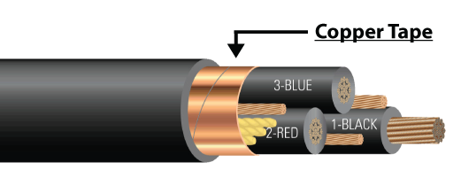
Copper Braid with Aluminum Foil
On smaller VFD loads, non-armoured cables with a copper braid shield are typically used. These cables do not commonly have symmetrical ground conductors and are easier to manage within smaller equipment terminations.
Conductor Insulation
On a typical 600V VFD system, the nominal voltage can have regular spikes (≥1000 per/sec) or transients up to 2,000 volts. Over time, these spikes can lead to extreme stress on the cable insulation. VFD cables are built with insulation that has been proven to operate in these conditions without degradation.
A thermoplastic insulation such as PVC contains a high dielectric constant value that results in increased cable capacitance and charging currents. This can be electrically demanding to the insulation over time and eventually can lead to cable failure. Therefore, an XLPE thermoset insulation with a low dielectric, engineered to withstand voltage spikes and hotspots is recommended for use in VFD cables.
EPR insulation is another material that can be used on VFD cables with voltage ratings ≥5000V. It has excellent electrical insulation properties for higher voltages and can be used in applications that require mechanical flexibility.
Symmetrical Grounds
The three symmetrical ground conductors are specifically located alongside each of the power conductors to lower induced voltage imbalances in the cable and also carry existing common mode noise back to the VFD. When a non-VFD cable (with only one large integral grounding conductor) is used in a VFD system, induced current and voltage potential will be more significant on the single ground conductor and less balanced inside the cable than if they were split across three separate symmetrical grounding conductors. See our Specialty Cable Catalogue for VFD Cable Specs and more information.

Speak to one of our wire & cable
specialists at a branch near you

Shop our full range of electrical
wire & cable and accessories

View our product & industry
catalogues & flyers

Apply today & join our team
Powered by Difference